A fluorescent lamp is a complex technical product. Its functioning is based on several physical principles. In order for the product to start working as a lamp that emits light, it is necessary to sequentially turn on the elements of its structure. To do this, you need to understand the question of how to connect a fluorescent lamp to an electrical network, and find out all the nuances in the working connection diagrams.
Read in the article
- 1 Fluorescent lamps
- 1.1 Device and principle of operation
- 1.2 Lamp start
- 1.3 Maintenance of working mode
- 2 Advantages and disadvantages of different types of ballasts
- 2.1 empra
- 2.2 electronic ballast
- 3 Features and order of the classic connection through an electromagnetic ballast
- 3.1 Wiring diagram for a fluorescent lamp with a choke
- 3.2 Scheme of a fluorescent lamp with two lamps
- 4 Features and order of connection through a modern electronic ballast
- 4.1 Turning on the electronic ballast for fluorescent lamps: scheme 36 w
- 4.2 Luminaire scheme 2 × 36 with electronic ballast
- 4.3 Circuit using voltage multipliers
- 5 System health check
- 6 Lamp replacement
- 7 Conclusion
Fluorescent lamps
Different light sources use different physical principles to create light emission. A tungsten wire glows brightly in an incandescent light bulb. Electricity is converted into heat, and heat energy into light. And all this - in one small tungsten spiral. In a fluorescent lamp, different physical processes take place in its different elements.

Device and principle of operation
A fluorescent lamp is a representative of a group of gas-discharge light sources. Outwardly, it is made in the form of a glass container of arbitrary shape - from a tube to a spiral with curls. The cylinder is filled with inert gas and mercury vapor. If an electric discharge is created in this volume, then ultraviolet radiation arises in mercury vapor.
A layer of phosphor is applied to the inner surface of the balloon. This is a substance that, under the influence of ultraviolet light, begins to glow in the visible spectrum. The technical task is to make the lamp glow continuously after pressing the "Start" button and until the moment the "Stop" button is pressed.
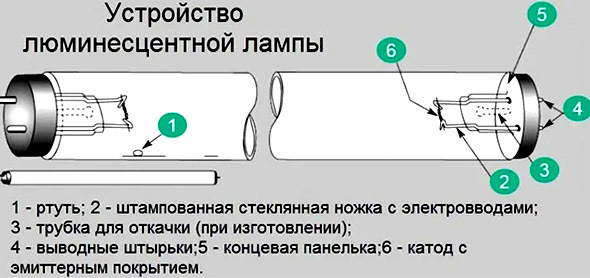
The lamp design includes two cathodes, output pins, an end panel, tubes for removing inert gas, mercury, a stamped glass leg, supplemented with electrical inputs, and other details. The cathodes have a tungsten helix.
Lamp start
To start the lamp into operation, you first need to connect voltage to its contacts. The filament will begin to heat up, and a stream of emitter particles will flow from it. Particles activate a mixture of inert gas and mercury vapor, the gas mixture will start ultraviolet radiation. The ultraviolet light activates the phosphor that coats the inner surface of the bulb, and visible light appears. The lamp is on.
The starting circuit is initially supplied with voltage. At first, the current will not pass through the lamp, as it is limited by the high resistance of the internal environment. It enters the cathode coils and heats them up. At the same time, the current goes to the starter and gives impetus to the formation of a glow discharge inside it. After the inductor contacts warm up under the action of the current, the bimetallic plate closes. As a result, the metal becomes a conductor and the discharge stops. At the next stage, the bimetallic electrode cools down, which leads to the opening of the contacts.
Maintenance of working mode
The "On" mode must continue until the "Turn off" command appears. As part of a fluorescent lamp, there are two functional devices - a choke and a starter.
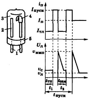
The starter is a glass container filled with an inert gas and containing two electrodes - a fixed and a bimetallic one. The starter closes and opens the electrical circuit and starts the ignition mechanism for the inert gas in the flask. A change in the temperature regime inside the starter leads to the separation of the bimetallic plate from the fixed electrode.
In the inductor, under the influence of self-induction, an increased voltage pulse arises, which breaks through the gas gap in the bulb. It gives impetus to the ignition of the lamp. The lamp will continue to work. This is the point of including a starter and a choke in the lamp control circuit.
Advantages and disadvantages of different types of ballasts
To limit the magnitude of the current in the gas discharge and prevent the failure of the electrodes due to this the circuits sequentially include a load, which is called differently: choke, ballast, ballast. These are representatives of the category of start-up and control equipment (PRA). Two types of ballasts exist and are used: electromagnetic and electronic.
empra
Electromagnetic ballast (electromechanical ballast - electronic ballast) was created on the basis of a transformer configuration. This is the same choke - a coil with a core. The throttle, when the contacts are opened, generates a voltage pulse with a large value, which ensures ignition. The gaseous medium in the bulb of the lamp emits ultraviolet, it irradiates the phosphor, which emits visible light.
electronic ballast
Electronic control gear is created on the basis of conventional electronic components: diodes, triodes, transistors, dinistors, etc. In this case, in one device, in one electronic circuit, the functions of both the throttle and the starter are implemented. The device is light, compact and cheap.
Electronic triggers have a good set of advantages over magnetic triggers. They work quickly and turn on the lamps. The included lamps do not flicker, and the devices operate silently. Heat losses are reduced. Optimal circuit design ensures a long service life.
The lamp with electronic ballast is multifunctional. It operates in four modes: on, preheat, ignition and combustion.
Features and order of the classic connection through an electromagnetic ballast
The development and improvement of the circuitry of ballasts for fluorescent lamps has led to the creation of a number of options for control gear and lamp connection schemes.
Wiring diagram for a fluorescent lamp with a choke
The inductor is connected in series with the fluorescent lamp, and its function is to limit the current flowing through the lamp electrodes. The inductor creates a safe current for a particular lamp to heat its electrodes when ignited.
The functions of the inductor are to maintain the uniformity of the discharge and adjust the current if necessary. At the moment when the lamp turns on, the inductor restrains the starting current, after heating the spiral filaments, it produces a peak voltage from self-induction and lights the lamp.
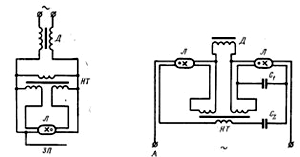
The inductor generates an increased voltage pulse, due to which a discharge occurs in the lamp bulb and stabilization of the electric discharge is ensured. In case of voltage deviations in the electrical network, the choke ensures uninterrupted operation of the lamp.
In transformer circuits for quick start-up of fluorescent lamps using as a ballast resistance choke, the initial heating of the cathodes is carried out by a filament transformer or autotransformer.
The features of a starterless connection include some specific points. Since ELRA is selected for a specific load, it is forbidden to connect a device designed for two lamps to one lamp. If the electronic ballast is connected to the network without load, the device will fail.
Scheme of a fluorescent lamp with two lamps
One lamp can consist of two simultaneously working lamps. In this case, each set is mounted in a certain sequence, and the sets are also mounted sequentially among themselves.
In luminaires consisting of two fluorescent lamps, two sets are connected in series. First, the phase wire is connected to the inductor input. Then the wire from the throttle output goes to one contact of the lamp 1, from the second contact it goes to the starter. From here there is a connection with the second pair of contacts of the same lamp 1, and the free contact is connected to the neutral power wire (N).
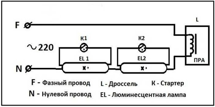
The second tube is also connected: first the throttle, from it - to one contact of the lamp 2, the second contact of the same group goes to the second starter, the starter output is connected to the second pair of contacts of the lighting device 2 and the free contact is connected to the neutral wire input.
Features and order of connection through a modern electronic ballast
Electronic ballast is considered a more modern and efficient solution. It is essential for the user that the working lamp almost does not blink and other technical characteristics are much higher.
Turning on the electronic ballast for fluorescent lamps: scheme 36 w
All work on the transition to a new electronic ballast consists in the fact that the old ballast and starter must be removed from the lamp structure and a new electronic ballast must be attached. Its input terminals are connected to the electrical network, and the output terminals are connected to the two poles of the lamp.
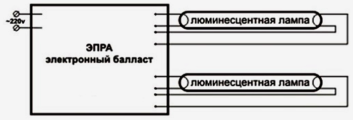
Luminaire scheme 2 × 36 with electronic ballast
The use of an electronic ballast allows electricians to create various options for turning on fluorescent lamps. Schemes with high or low coefficient of performance (COP) have been developed, for greater or lesser lamp power. Lamps work great with any kind of electronics.
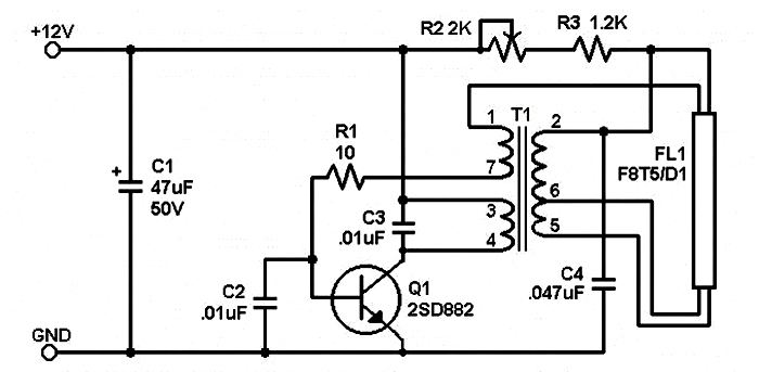
Circuit using voltage multipliers
A voltage multiplier is a fragment of an electronic circuit consisting of a capacitor and a diode. An open diode allows the capacitor to charge to a level where it can power the load. If there is no load, the accumulated voltage is maintained, the diode no longer opens.
The multiplier can light the lamp, while he himself at this time performs the function of a rectifier. The voltage multiplier can turn on the fluorescent light source in the absence of a choke valve and a starter. Its role is to extend the life of burned-out lamps. This circuit remains operational even with burnt filaments, since the conclusions are closed to each other. If the multiplier produces enough voltage to start, the lamp will light up.
The scheme is not designed for long-term operation, it helps out in emergency and emergency situations. Even burnt-out devices are able to work for some time at powers not exceeding 40 watts.
Attention! Worker health authorities do not recommend using this in residential areas, workshops or garages due to the high flicker factor.
System health check
Each newly created product (and any technical product is) after production should be tested. This is a complex process consisting of checks for safety, operation, completeness of capabilities, compliance with technical standards and regulations.
Functional testing provides complete information about the current state of the tested product, as well as a detailed description of the shortcomings and the prospects for their elimination. The analysis takes into account the specifics of the product and its requirements.
Fluorescent lamps have a tungsten filament in their composition. To increase its durability, the thread is covered with a layer of active alkali metal. But with frequent and numerous switching on and off, the protective coating crumbles and the thread burns out. You can easily check if the filament is intact with a multimeter. If the bulb is leaking, air enters the bulb and the bulb must be replaced.
A throttle malfunction is detected by its buzzing, flickering of the lamp, the appearance of “snakes” inside the lamp, too short operation after switching on. A burnt throttle smells burnt, it cannot be repaired, you just need to change it
Lamp replacement
Lamps with a G5, G13 base are popular with users. Sometimes there is a defect in the lamp itself, sometimes the throttle or starter is faulty. When replacing with a serviceable one, you must first de-energize the lamp, remove the cover, then remove the lamp by turning it 900 and pulling slightly. Buy the same new one and insert it in the same place. You can connect the electricity and check that everything worked. But if the new lamp does not work, there is every reason to suspect the throttle. Its removal and replacement require special knowledge and skills. And the cost will be high, almost equal to the cost of the lamp itself.
Conclusion
Daylight fluorescent lamps are more economical than traditional incandescent lamps, but their performance requires regular checks, and flickering can harm the eyes. It is more convenient to work with LED lamps, but they are more expensive. This technique is constantly being improved and updated. You just need to follow the information.
I've been looking at buying a sauna for a long time. I recently found exactly that one at an exhibition in Zyablikovo ...
A friend designed a garage for me. It remains only to find a team for implementation. Well on…
Guys, it's not complete. You don't mention Domorost, but still these guys have a problem...
Hello, thank you for the informative information. Health to you and your loved ones. Sk…
From strong winds, fences sometimes fall if they are installed unreliably. We have our own at Terem-p ...
We bought a summer cottage with a dilapidated country house. They restored it through the tower. AND …
The tm film and the zebra have nothing to do with PLEN, do not mislead people ...
We need this Vodonaeva with her cats like fifth leg dogs.
I need to make a Christmas tree out of cardboard for the office. If you do this please give me a call...
Don't chase the blizzard... In your opinion, all the great writers were prostitutes. Go...
Hello! And how can you make a cone planter for flowers, or rather, how to fasten the cone?
Four days ago I ordered a Revolts heating kit for our dacha. I'm going to pick up tomorrow...
If the apartment is ready, then why doesn’t Buzova broadcast to the whole world about moving and living ...
Like 10m. Enough tape for 1.5m of fence?!
This is most likely an Internet modem like yota. And, I remember, they used both polarizers ...


